ULTRON — ROS-Based Unmanned Ground Vehicle
Home
This repository focuses on documenting a ROS-based UGV system that I developed. The system utilizes a Raspberry Pi (3B+) along with a camera, lidar, and motors to provide basic functionality. The Raspberry Pi runs Ubuntu 16.04 LTS with ROS Kinetic pre-installed via an image from Ubiquity Robotics. Follow their documentation to understand more about uploading the image to the Raspberry Pi. The workstation also runs Ubuntu 16.04 LTS with ROS Kinetic, which can be setup following this documentation.
Rationale
This repository focuses on documenting a ROS-based UGV system that I developed. The system utilizes a Raspberry Pi (3B+) along with a camera, lidar, and motors to provide basic functionality. The Raspberry Pi runs Ubuntu 16.04 LTS with ROS Kinetic pre-installed via an image from Ubiquity Robotics. Follow their documentation to understand more about uploading the image to the Raspberry Pi. The workstation also runs Ubuntu 16.04 LTS with ROS Kinetic, which can be setup following this documentation.
Features
To understand the purpose of this project, it is imperative to delve into the intended functionalities of the robot. The feature table serves as a guiding framework, precisely delineating the sub-goals of ULTRON. It is also important to note that while I have developed certain components of the software, not all of it is my intellectual property. I am committed to diligently documenting all sources and attributing them appropriately.
| Feature | Description | Package(s) | Status |
|---|---|---|---|
| Teleoperation | Workstation has control over the robot remotely. | exmachina (dev) & rosserial (git) |
✅ |
| Vision | Workstation has the ability to see visual feedback from the robot remotely. | raspicam_node (git) & rqt_image_view (git) |
✅ |
| LiDAR | Workstation has the ability to detect a surface with a laser and measure the time for the reflected light to return to the receiver. | ydlidar (web) & rviz (git) |
✅ |
| Map Making | Workstations can use the robot to build a map and localize at the same time. | hector_slam (git) |
✅ |
| Person Detection | Workstation can observe the robot detecting the "location of the person" as an object and marking the area in which the person is located. | opencv (git) & rqt_image_view (git) |
🔜 |
| Path Planning | Workstation provides a destination, and the robot finds the shortest and most obstacle-free path from the start to goal state. | N/A | 🔜 |
Materials
Here is a quick overview of the list of main electrical and mechanical components used to create ULTRON:
Electrical Components
| Component | Price |
|---|---|
| 64GB Micro SD Card x1 | $5 |
| Raspberry Pi 3 Model B+ x1 | $35 |
| Arduino Mega 2560 REV3 x1 | $36 |
| YDLIDAR X2L x1 | $70 |
| DC 12V 120RPM Gear Motor x4 | $60 |
| L298N Motor Driver x2 | ~$20 |
| 1080P Webcam 5MP OV5647 x1 | ~$10 |
| 12V 2000mAh Battery x1 | ~$20 |
| LM2596 Adjustable DC-DC Step Down Buck Power Convert Module 4.0-40V Input to 1.25-37V x1 | $5 |
Mechanical Components
| Component | Price |
|---|---|
| Mecanum Wheels x4 | ~$20 |
| M4 x 60 mm F Hexconnector x6 | ~$10 |
Total Cost: $291
Note: some prices are based on wholesale price
3D Model
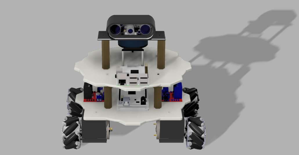
ULTRON's chassis frame was designed using Autodesk Fusion 360; here is a rendered representation. For more information on how to get started with a similar robot chassis design, refer to the first page of the wiki.
1. Building A Mechanical Chassis
Initial Sketch
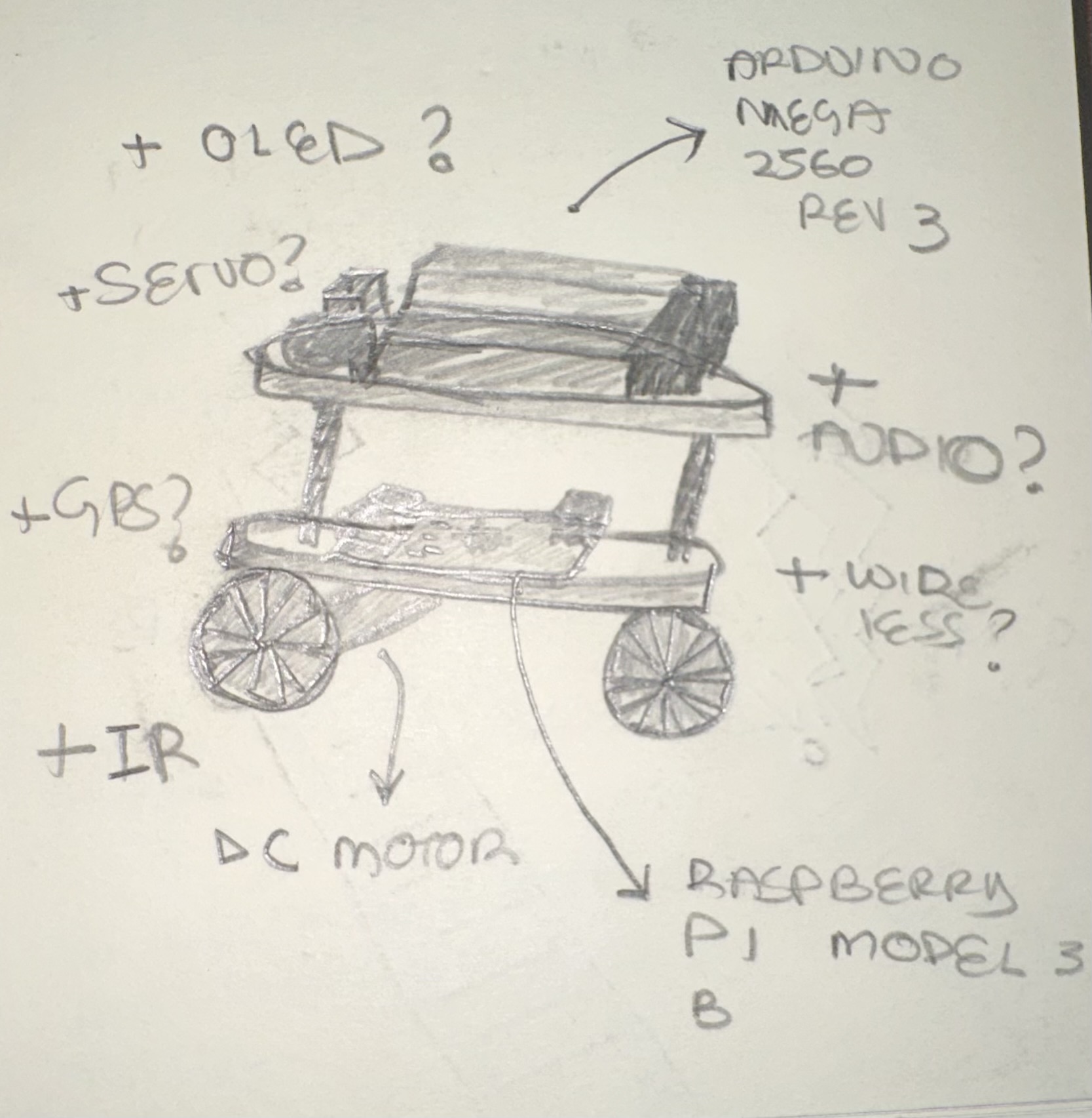
During ULTRON's design phase, a hand-drawn sketch was created to outline the essential components of the robot. The Raspberry Pi 3 B+ and Arduino Mega Rev 2560 were chosen as the main components, setting the project's initial limitations. While the sensors and controller modules will significantly enhance the robot, the core system is already defined. With this foundation established, the focus can now shift to constructing the physical chassis for ULTRON. Six pieces were 3D printed for this project using the Pulse XE 3D printer from MatterHacker.
Fusion360 Design
To acquire the necessary skills for designing the mechanical chassis of my robot, I referred to a YouTube tutorial titled "How to Design a Robot in FUSION 360 for ROS Simulation || Beginner Tutorial - Autodesk Fusion 360" by Pranshu Tople. After successfully replicating the robot in Fusion 360, I applied similar techniques to create ULTRON.
ULTRON's STL File(s):
1x chassis_bottom
2x 120rpm_greartisan_motor_support_L
2x 120rpm_greartisan_motor_support_R
6x hexconnector
Note: The hexconnectors are not accurate in size and are meant to replicate the real hexconnectors.
When working on similar UGV projects, I recommend selecting the motors beforehand. Having them on hand is convenient but you can still work with the motor's dimensions outlined in the datasheet. For ULTRON, I chose the 12V 120RPM Greartisan gear motors and found a suitable 3D model on GrabCAD.
1x Raspberry Pi 3 B+
1x Arduino Mega REV 2560
2. Wiring A Robot
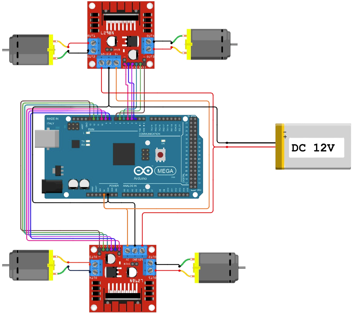
Arduino Mega 2560 Rev3 + L298N Motor Wiring Setup
Connection Guide:
- 5V pin on Arduino Mega 2560 to 5V pin on both motor drivers.
- GND pin on Arduino Mega 2560 to GND pin on both motor drivers.
- Pin 2 to DC1IN1, Pin 3 to DC1IN2, Pin 4 to DC1ENA.
- Pin 5 to DC1IN3, Pin 6 to DC1IN4, Pin 7 to DC1ENB.
- Pin 8 to DC2IN1, Pin 9 to DC2IN2, Pin 10 to DC2ENA.
- Pin 11 to DC2IN3, Pin 12 to DC2IN4, Pin 13 to DC2ENB.
These connections allow you to control the motors effectively using the Arduino Mega 2560 and L298N motor driver. We'll demonstrate this with a working code example and a short demo video showcasing the motor functionality.
Next, we'll connect the Arduino Mega to the Raspberry Pi and utilize two ROS packages to develop the teleoperation feature: exmachina (dev) & rosserial (git). This combination enables us to send keyboard input to the robot, which the microcontroller can interpret in various ways. In this case, we use it to drive the motors.
| Arduino Mega 2560 PINS | L298N Driver DC1/DC2 PINS | Color Scheme |
|---|---|---|
| 5V | 5V (both drivers) | Red |
| GND | GND (both drivers) | Black |
| 2 | DC1IN1 | Orange |
| 3 | DC1IN2 | Yellow |
| 4 | DC1ENA | Green |
| 5 | DC1IN3 | Blue |
| 6 | DC1IN4 | Purple |
| 7 | DC1ENB | Pink |
| 8 | DC2IN1 | Orange |
| 9 | DC2IN2 | Yellow |
| 10 | DC2ENA | Green |
| 11 | DC2IN3 | Blue |
| 12 | DC2IN4 | Purple |
| 13 | DC2ENB | Pink |
Arduino Mega 2560 Rev3 + L298N Motor Coding Setup
The relevant source file for this phase of the project is the arduino_ws/ultron_move.ino (C++).
Motor Pin Definitions:
In this segment, the code defines constants for the pins used to control the motors of a robot. Each motor requires four input pins (IN1, IN2, IN3, IN4) to control the direction and two enable pins (ENA, ENB). The constants are given meaningful names like DC1IN1, DC1IN2, etc., to represent the specific pins connected to Motor 1, and similar constants for Motor 2.
// Definitions for Motor Pins
const int DC1IN1 = 2;  // Motor 1, Input 1
const int DC1IN2 = 3;  // Motor 1, Input 2
const int DC1IN3 = 5;  // Motor 1, Input 3
const int DC1IN4 = 6;  // Motor 1, Input 4
const int DC1ENA = 4;  // Motor 1, Enable A
const int DC1ENB = 7;  // Motor 1, Enable B

const int DC2IN1 = 8;  // Motor 2, Input 1
const int DC2IN2 = 9;  // Motor 2, Input 2
const int DC2IN3 = 11; // Motor 2, Input 3
const int DC2IN4 = 12; // Motor 2, Input 4
const int DC2ENA = 10; // Motor 2, Enable A
const int DC2ENB = 13; // Motor 2, Enable B
Setup Function:
The setup function is a special function in Arduino that runs once when the program starts. In this segment, the code begins serial communication at a baud rate of 9600, which allows communication with a computer for debugging or sending data. It then sets all the motor pins as outputs using the pinMode function. This step is necessary to ensure that the pins are configured correctly for motor control.
void setup() {
  Serial.begin(9600);

  // Set all motor pins as outputs
  pinMode(DC1IN1, OUTPUT);
  pinMode(DC1IN2, OUTPUT);
  pinMode(DC1IN3, OUTPUT);
  pinMode(DC1IN4, OUTPUT);
  pinMode(DC1ENA, OUTPUT);
  pinMode(DC1ENB, OUTPUT);
  pinMode(DC2IN1, OUTPUT);
  pinMode(DC2IN2, OUTPUT);
  pinMode(DC2IN3, OUTPUT);
  pinMode(DC2IN4, OUTPUT);
  pinMode(DC2ENA, OUTPUT);
  pinMode(DC2ENB, OUTPUT);
}
Loop Function:
The loop function in Arduino repeatedly runs after the setup function. In this code segment, a test routine for the robot "ULTRON" is defined. It involves a sequence of movements with pauses in between. The wait function is used to stop the motors, and then a 3-second delay is introduced using delay(3000) to pause the robot.
Next, the forward, backward, left, and right functions are called one by one to make "ULTRON" move forward, backward, left, and right, respectively. Following each movement, the wait function is called again to stop the robot, and a 3-second delay is added to pause before the next movement.
Overall, the loop function controls the execution of the test routine, allowing "ULTRON" to perform a series of movements and pauses continuously.
void loop() {
  // Test Routine
  wait();              // Stop the motors
  delay(3000);         // Delay 3 seconds

  forward();           // Move ULTRON forward
  delay(3000);         // Delay 3 seconds

  wait();              // Stop the motors
  delay(3000);         // Delay 3 seconds

  backward();          // Move ULTRON backward
  delay(3000);         // Delay 3 seconds

  wait();              // Stop the motors
  delay(3000);         // Delay 3 seconds

  left();              // Turn ULTRON left
  delay(3000);         // Delay 3 seconds

  wait();              // Stop the motors
  delay(3000);         // Delay 3 seconds

  right();             // Turn ULTRON right
  delay(3000);         // Delay 3 seconds

  wait();              // Stop the motors
  delay(3000);         // Delay 3 seconds
}
Motor Control Functions:
This segment contains four functions: forward, backward, left, and right, responsible for controlling specific movements of "ULTRON." These functions use the analogWrite function to set the motor speed by providing PWM signals to the enable pins (ENA and ENB) with a value of 200.
In each motor control function, specific input combinations are set on the input pins (IN1, IN2, IN3, IN4) to determine the direction of rotation for each wheel, enabling "ULTRON" to move forward, backward, turn left, or turn right. The wait function is utilized to stop the robot by setting the speed to zero and ensuring all input pins are set to LOW, effectively halting all motors.
// Function to move ULTRON forward
void forward(void) {
  analogWrite(DC1ENA, 200); analogWrite(DC1ENB, 200);
  analogWrite(DC2ENA, 200); analogWrite(DC2ENB, 200);
  digitalWrite(DC1IN1, HIGH); digitalWrite(DC1IN2, LOW);
  digitalWrite(DC1IN3, LOW);  digitalWrite(DC1IN4, HIGH);
  digitalWrite(DC2IN1, HIGH); digitalWrite(DC2IN2, LOW);
  digitalWrite(DC2IN3, LOW);  digitalWrite(DC2IN4, HIGH);
}

// Function to move ULTRON backward
void backward(void) {
  analogWrite(DC1ENA, 200); analogWrite(DC1ENB, 200);
  analogWrite(DC2ENA, 200); analogWrite(DC2ENB, 200);
  digitalWrite(DC1IN1, LOW);  digitalWrite(DC1IN2, HIGH);
  digitalWrite(DC1IN3, HIGH); digitalWrite(DC1IN4, LOW);
  digitalWrite(DC2IN1, LOW);  digitalWrite(DC2IN2, HIGH);
  digitalWrite(DC2IN3, HIGH); digitalWrite(DC2IN4, LOW);
}

// Function to turn ULTRON left
void left(void) {
  analogWrite(DC1ENA, 200); analogWrite(DC1ENB, 200);
  analogWrite(DC2ENA, 200); analogWrite(DC2ENB, 200);
  digitalWrite(DC1IN1, HIGH); digitalWrite(DC1IN2, LOW);
  digitalWrite(DC1IN3, HIGH); digitalWrite(DC1IN4, LOW);
  digitalWrite(DC2IN1, LOW);  digitalWrite(DC2IN2, HIGH);
  digitalWrite(DC2IN3, LOW);  digitalWrite(DC2IN4, HIGH);
}

// Function to turn ULTRON right
void right(void) {
  analogWrite(DC1ENA, 200); analogWrite(DC1ENB, 200);
  analogWrite(DC2ENA, 200); analogWrite(DC2ENB, 200);
  digitalWrite(DC1IN1, LOW);  digitalWrite(DC1IN2, HIGH);
  digitalWrite(DC1IN3, LOW);  digitalWrite(DC1IN4, HIGH);
  digitalWrite(DC2IN1, HIGH); digitalWrite(DC2IN2, LOW);
  digitalWrite(DC2IN3, HIGH); digitalWrite(DC2IN4, LOW);
}

// Function to stop ULTRON
void wait(void) {
  analogWrite(DC1ENA, 0); analogWrite(DC1ENB, 0);
  analogWrite(DC2ENA, 0); analogWrite(DC2ENB, 0);
  digitalWrite(DC1IN1, LOW); digitalWrite(DC1IN2, LOW);
  digitalWrite(DC1IN3, LOW); digitalWrite(DC1IN4, LOW);
  digitalWrite(DC2IN1, LOW); digitalWrite(DC2IN2, LOW);
  digitalWrite(DC2IN3, LOW); digitalWrite(DC2IN4, LOW);
}
Arduino Mega 2560 Rev3 + L298N Motor Demo
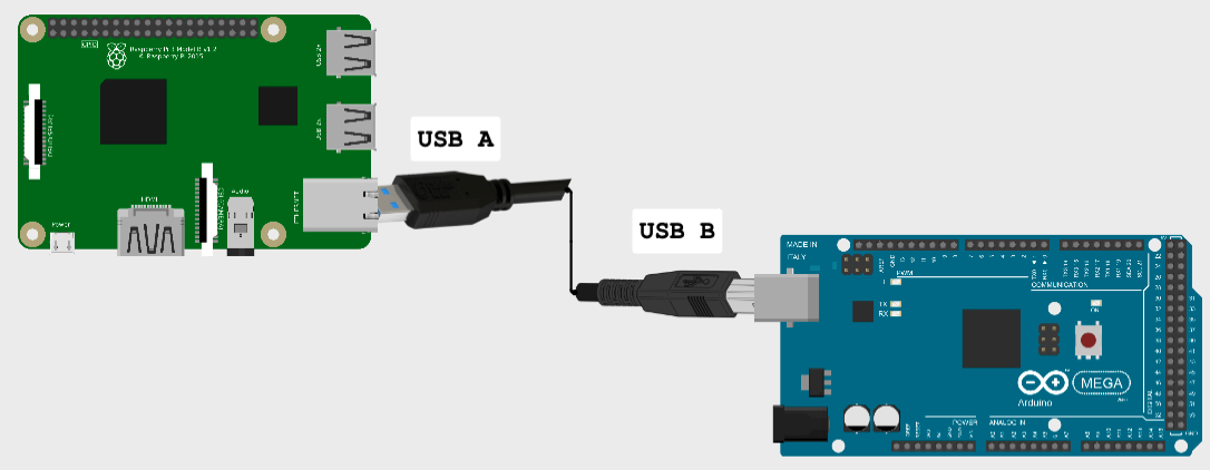
Raspberry Pi 3 (B+) + Arduino Mega 2560 Rev3 Wiring Setup
In this project, we establish a simple connection between the main computer and the microcontroller using a standard USB-A to USB-B wire. This connection facilitates seamless communication between the devices through the widely-used serial communication protocols provided by the rosserial (git) package. To aid in documentation, a diagram has been included to represent the setup visually.
The instructions on developing teleoperation for your robot can be referred to in order to replicate the demo.
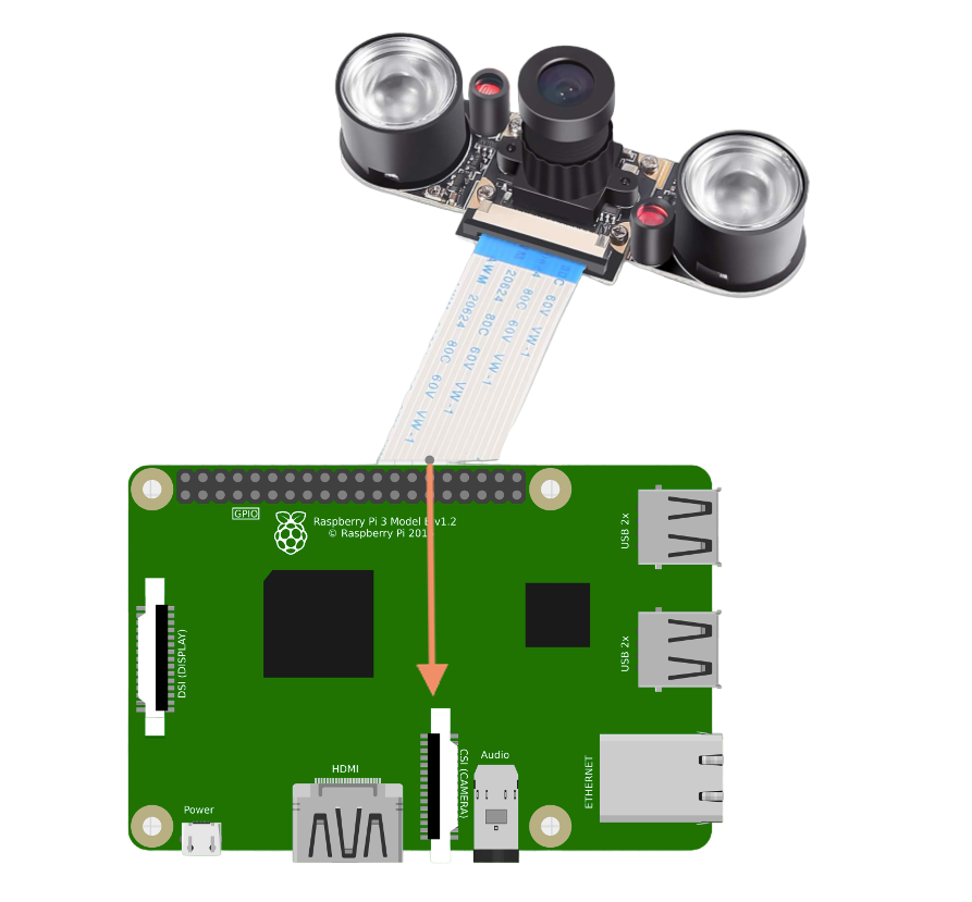
Raspberry Pi 3 (B+) + 1080P Webcam 5MP OV5647 Wiring Setup
In this project, the OV5647 camera module is connected to the Raspberry Pi's CSI port, utilizing the raspicam package within the ROS (Robot Operating System) environment. To view the camera's visual output in real-time, we utilize the rqt_image_view ROS node. The camera publishes its images on the /raspicam_node/image/compressed topic. By running the rqt_image_view node and subscribing to this topic, we can observe the live visual output from the OV5647 camera in the GUI window. This real-time image stream enhances the project's capabilities, enabling tasks like object detection, image processing, and computer vision-based applications.
The instructions on developing vision for your robot can be referred to in order to replicate the demo.
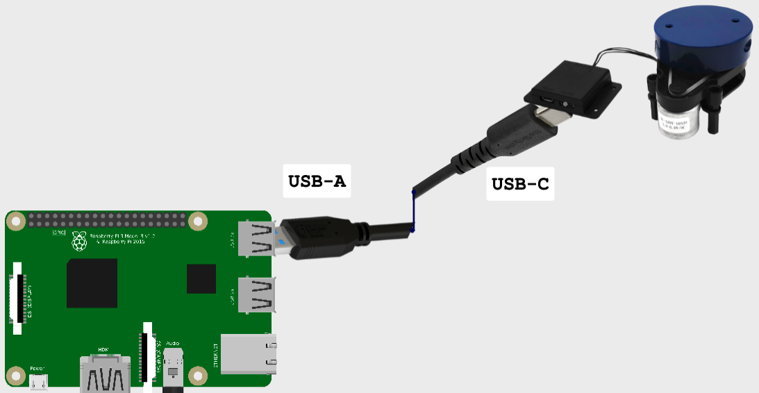
Raspberry Pi 3 (B+) + YDLiDAR X2L Wiring Setup
In this project, the YDLiDAR X2L LiDAR sensor is connected to the Raspberry Pi using the ydlidar ROS package. The package serves as the interface driver, facilitating communication with the sensor. LiDAR data is visualized in real-time through rviz, offering a 3D view of the surroundings. The continuous scanning of the YDLiDAR X2L enables SLAM, obstacle detection, and navigation.
The instructions on developing lidar for your robot can be referred to in order to replicate the demo.
3. Feature: Teleoperation
Teleoperation, also called remote control, involves controlling a machine from a distance. It enables a human operator to interact with a remote entity without being physically present. In this project, it is facilitated by the Robot Operating System (ROS), an open-source middleware framework.
We use two ROS packages: exmachina (dev) & rosserial (git). Once we launch a roscore, a collection of nodes and programs required for a ROS-based system, we can run commands to execute the nodes and programs in the package. Let's examine the packages.
Remote Keyboard Control with exmachina package
exmachina# 1. Clone Repo $ git clone git@github.com:FAAMT/ros_ugv_ultron.git # 2. Run Node $ rosrun exmachina exmachina.py
The node was designed to read keyboard input and publish it to a topic named keyboard_input. The script initializes a ROS node called exmachina and sets up a publisher to the keyboard_input topic, using the rospy.Publisher function from the ROS Python library.
#!/usr/bin/env python
import rospy
import sys
from std_msgs.msg import String
from sys import stdin
import getch
import time
The following functions are defined to facilitate the node's operation:
def keyboard_input_pub():
    pub = rospy.Publisher('keyboard_input', String, queue_size=1)
    rospy.init_node('exmachina', anonymous=True)
    return pub

def exmachina_init_rate():
    rate = rospy.Rate(1000) # 1hz
    return rate
The main part of the script:
if __name__ == '__main__':
    pub_0 = keyboard_input_pub()
    rate = exmachina_init_rate()

    try:
        while(1):
            msg = getch.getch()
            if(msg == "" or msg == ""):
                break
            pub_0.publish(msg)
            rospy.loginfo(msg)

    except rospy.ROSInterruptException:
        pass
The script continuously listens for keyboard input and publishes the received characters to the keyboard_input topic. It runs at a rate of 1000 Hz, reading input and publishing until Ctrl+C or Ctrl+Z is pressed to terminate it. This enables remote robot control through keyboard inputs in the ROS environment.
Note: If using this package, ensure that the exmachina.py script uses the actual Ctrl+C or Ctrl+Z keys in the if statement if(msg == "" or msg == ""): to avoid an infinite loop.
Serial Communication with rosserial_python Package
rosserial_python# 1. Clone Repo (noetic branch) $ git clone https://github.com/ros-drivers/rosserial.git # 2. Run Node (Arduino Mega 2560) $ rosrun rosserial_python serial_node.py /dev/ttyACM0 _baud:=57600
The rosserial_python package facilitates serial communication between ROS and microcontrollers, enabling seamless integration of low-level microcontroller code with ROS. This integration simplifies the control and interaction of robots and devices.
Arduino Mega 2560 ROS Publisher & Subscriber
The relevant source file for this phase of the project is the arduino_ws/ultron_teleoperation.ino (C++).
After verifying the correct wiring and functionality of the Arduino Mega 2560, as demonstrated in the Wiring A Robot page, we can proceed to configure the essential Arduino ROS publishers and subscribers for teleoperation.
Library Inclusions and ROS Node Setup:
This segment includes the necessary libraries for the project, such as ROS (Robot Operating System) and standard message types. It initializes the ROS node handle.
#include <ros.h>
#include <std_msgs/String.h>
#include <Arduino.h>
#include <HardwareSerial.h>

ros::NodeHandle nh;
Subscriber Callback:
The keyboard_input callback function is established here. It handles incoming messages from the keyboard_input topic and stores the received data in the data variable.
std_msgs::String data;
std_msgs::String str_msg;

void keyboard_input(const std_msgs::String& key){
  Serial.println("Heard Something");
  data.data = key.data;
}
ros::Subscriber<std_msgs::String> key("keyboard_input", &keyboard_input);
Additional Movement Functions:
This section contains new functions added for motor capability, such as rotating left and rotating right.
void rotateleft(void){
  analogWrite(DC1ENA, 255); analogWrite(DC1ENB, 255);
  analogWrite(DC2ENA, 255); analogWrite(DC2ENB, 255);
  digitalWrite(DC1IN1, HIGH); digitalWrite(DC1IN2, LOW);   // Wheel 1
  digitalWrite(DC1IN3, LOW);  digitalWrite(DC1IN4, HIGH);  // Wheel 2
  digitalWrite(DC2IN1, LOW);  digitalWrite(DC2IN2, HIGH);  // Wheel 3
  digitalWrite(DC2IN3, HIGH); digitalWrite(DC2IN4, LOW);   // Wheel 4
}

void rotateright(void){
  analogWrite(DC1ENA, 255); analogWrite(DC1ENB, 255);
  analogWrite(DC2ENA, 255); analogWrite(DC2ENB, 255);
  digitalWrite(DC1IN1, LOW);  digitalWrite(DC1IN2, HIGH);  // Wheel 1
  digitalWrite(DC1IN3, HIGH); digitalWrite(DC1IN4, LOW);   // Wheel 2
  digitalWrite(DC2IN1, HIGH); digitalWrite(DC2IN2, LOW);   // Wheel 3
  digitalWrite(DC2IN3, LOW);  digitalWrite(DC2IN4, HIGH);  // Wheel 4
}
Setup Function:
This segment sets up the initial configurations for the ULTRON robot. It sets all the required pins to OUTPUT mode for motor control. It initializes the ROS node, subscribes to the keyboard_input topic, and starts serial communication.
void setup() {
  pinMode(DC1IN1, OUTPUT); pinMode(DC1IN2, OUTPUT);
  pinMode(DC1IN3, OUTPUT); pinMode(DC1IN4, OUTPUT);
  pinMode(DC1ENA, OUTPUT); pinMode(DC1ENB, OUTPUT);
  pinMode(DC2IN1, OUTPUT); pinMode(DC2IN2, OUTPUT);
  pinMode(DC2IN3, OUTPUT); pinMode(DC2IN4, OUTPUT);
  pinMode(DC2ENA, OUTPUT); pinMode(DC2ENB, OUTPUT);

  nh.initNode();
  nh.subscribe(key);
  Serial.begin(57600);
}
Command Strings and Motion Control:
This segment defines strings that represent different commands, such as moving forward, backward, left, right, stopping, rotating left, and rotating right. In the main loop, the code reads the data received from the keyboard_input topic and performs the corresponding action based on the command strings.
String move_forward  = "w";
String move_backward = "s";
String move_left     = "a";
String move_right    = "d";
String rotate_right  = "e";
String rotate_left   = "q";
String stop          = "x";
int motion_period = 50;

void loop(){
  Serial.println("Device Active");
  const String input = data.data;
  delay(10);
  if(rotate_right.compareTo(input) == 0){
    str_msg.data = "Rotating right!";
    rotateright(); delay(motion_period / 4); wait();
  }
  else if(rotate_left.compareTo(input) == 0){
    str_msg.data = "Rotating left!";
    rotateleft(); delay(motion_period / 4); wait();
  }
  else if(stop.compareTo(input) == 0){
    str_msg.data = "Stopping!";
    wait(); delay(motion_period);
  }
  else if(move_forward.compareTo(input) == 0){
    str_msg.data = "Moving forward!";
    forward(); delay(motion_period); wait();
  }
  else if(move_backward.compareTo(input) == 0){
    str_msg.data = "Moving backward!";
    backward(); delay(motion_period); wait();
  }
  else if(move_right.compareTo(input) == 0){
    str_msg.data = "Moving right!";
    right(); delay(motion_period); wait();
  }
  else if(move_left.compareTo(input) == 0){
    str_msg.data = "Moving left!";
    left(); delay(motion_period); wait();
  }
  nh.spinOnce();
}
Demo Video: Teleoperation
Demo Video: Teleoperation with Camera Feed
4. Feature: Vision
Vision refers to the ability of a robot or an autonomous system to perceive and interpret its surrounding environment using visual data. Vision plays a crucial role in enabling robots to interact and navigate in the world.
We use two ROS packages: raspicam_node (git) & rqt_image_view (git).
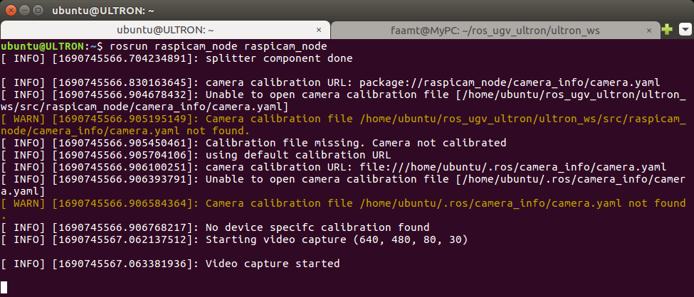
Interfacing with the 1080P MP5 OV5647 using the raspicam_node Package
raspicam_node# 1. Clone Repo (kinetic branch) $ git clone https://github.com/UbiquityRobotics/raspicam_node.git # 2. Run Node $ rosrun raspicam_node raspicam_node
The raspicam_node from Ubiquity Robotics is a ROS node that plays a significant role in leveraging vision capabilities for robots using Raspberry Pi and the Raspberry Pi Camera (specifically, the Raspberry Pi Camera Module or the Raspberry Pi HQ Camera). The raspicam_node acts as an interface between the Raspberry Pi Camera and the ROS ecosystem, allowing ROS-based robots to access and utilize the camera's visual data effectively.
Check out Ubiquity Robotics' official repository and their helpful documentary for in-depth insights into the raspicam_node package.
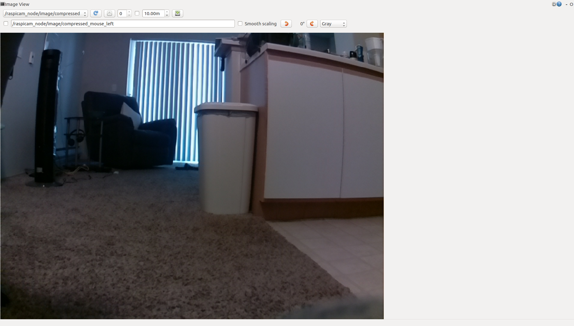
Visual Data Representation with rqt_image_view Package
rqt_image_view# 1. Clone Repo $ git clone https://github.com/ros-visualization/rqt_image_view # 2. Run Node (subscribe to /raspicam_node/image/compressed) $ rosrun rqt_image_view rqt_image_view
The rqt_image_view is a ROS package that provides a graphical interface for visualizing images published on specific ROS topics. It allows real-time viewing of camera streams, LiDAR data, and other image-related information in ROS. Users can zoom, pan, and analyze the images, making it useful for robotics and computer vision projects.
Camera Configuration using Launch Files
A launch file is a convenient tool for defining and organizing the configuration needed to initiate either a full ROS system or specific components. In our case, we can utilize it to set up the camera according to our project's requirements. The launch file allows us to adjust various parameters essential for camera configuration. Here are the key parameters relevant to our project:
enable_raw: Boolean, default: "true".enable_imv: Boolean, default: "false".camera_id: Integer, default: "0".camera_frame_id: String, default: "raspicam".camera_name: String, default: "camerav2_320x240".camera_info_url: String, default: "package://raspicam_node/camera_info/camerav2_320x240.yaml".width: Integer, default: "320".height: Integer, default: "240".framerate: Integer, default: "30".exposure_mode: String, default: "antishake".shutter_speed: Integer, default: "0" (auto).
Camera Parameters:
<arg name="enable_raw" default="true"/>
<arg name="enable_imv" default="false"/>
<arg name="camera_id" default="0"/>
<arg name="camera_frame_id" default="raspicam"/>
<arg name="camera_name" default="camerav2_320x240"/>
Nodes — raspicam_node:
<node type="raspicam_node" pkg="raspicam_node" name="raspicam_node" output="screen">
  <param name="camera_frame_id" value="$(arg camera_frame_id)"/>
  <param name="enable_raw" value="$(arg enable_raw)"/>
  <param name="enable_imv" value="$(arg enable_imv)"/>
  <param name="camera_id" value="$(arg camera_id)"/>
  <param name="camera_info_url" value="package://raspicam_node/camera_info/camerav2_320x240.yaml"/>
  <param name="camera_name" value="$(arg camera_name)"/>
  <param name="width" value="320"/>
  <param name="height" value="240"/>
  <param name="framerate" value="30"/>
  <param name="exposure_mode" value="antishake"/>
  <param name="shutter_speed" value="0"/>
</node>
In summary, this ROS launch file sets up the camera for robot ULTRON, and you can adjust the specified parameters to customize the camera's behavior as needed. The reason for configuring the camera is to utilize the opencv package for object detection in the next phase of the project.
Demo Video: Camera + LiDAR
5. Feature: LiDAR
The LiDAR feature enables a robot or autonomous system to perceive and interpret its surrounding environment using laser scan data. It plays a crucial role in enabling robots to interact and navigate in the world.
For LiDAR-based perception, we utilize two essential ROS packages: ydlidar (git) for interfacing with the YDLIDAR sensor series, and rviz (git) for 3D visualization of the laser scan data. Together, these packages empower the robot to gain valuable insights into its surroundings, supporting tasks like SLAM, obstacle detection, and navigation.
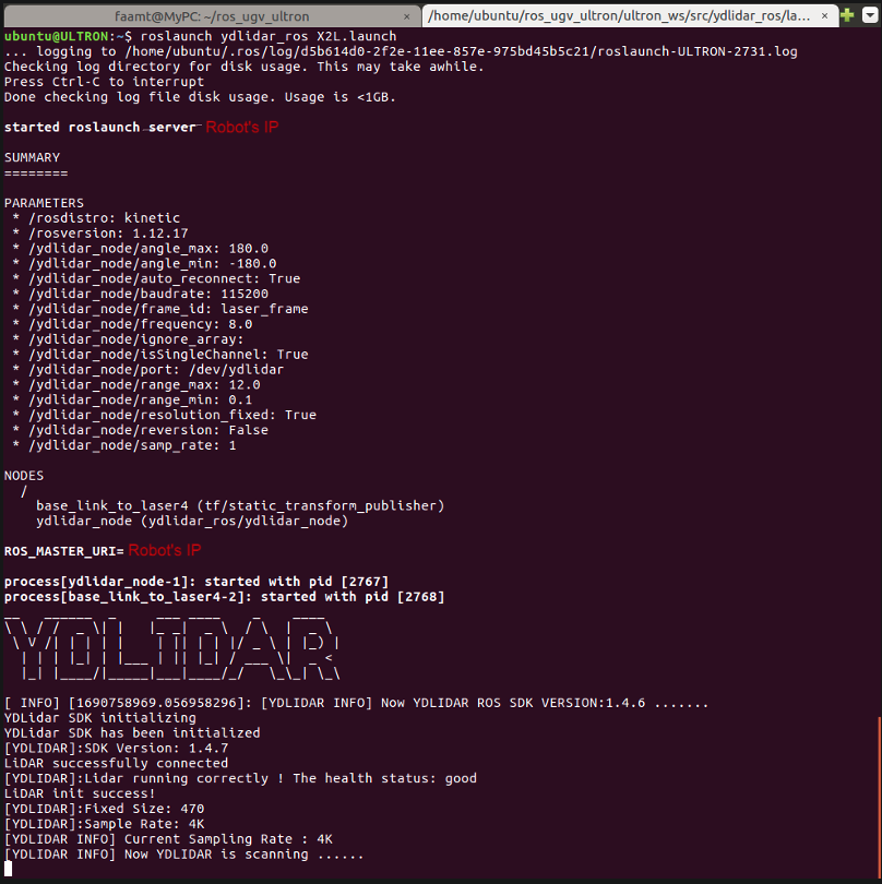
Interfacing with the YDLiDAR X2L using the ydlidar Package
ydlidar# 1. Download zip from ydlidar.com/downloads, extract to ~/catkin_ws/src # 2. Build Workspace $ cd ~/catkin_ws && catkin_make # 3. Launch $ roslaunch ydlidar_ros X2L.launch
The ydlidar package is a ROS driver specifically designed to interface with the YDLIDAR series of LiDAR sensors, including models like YDLIDAR X2L. The package provides the necessary functionality to access distance measurements from the LiDAR sensor.
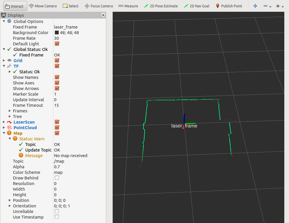
Laser Data Representation with rviz Package
rviz# 1. Install via apt $ sudo apt-get install ros-<ROS-DISTRO>-rviz # 2. Run (subscribe to /scan for laser data) $ rosrun rviz rviz
rviz is a ROS package that provides a graphical interface for visualizing various data, including laser scan data and images from specific ROS topics. It offers real-time viewing, zooming, panning, and analysis of sensor data, making it ideal for robotics and computer vision projects.
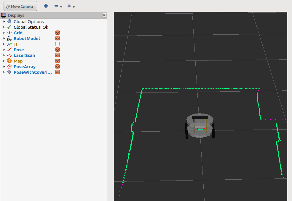
Unified Robot Description Format (URDF) with rviz Package
URDF (Unified Robot Description Format) is an XML-based file format in ROS used to describe a robot's kinematic and visual properties. It enables standardized representation for visualization, simulation, and control in ROS-based robotics.
The relevant source file for this phase of the project is the mypc_ws/src/ultron_desc/urdf/ultron.urdf (XML).
Let's break down the URDF code for the robot step by step:
<?xml version='1.0'?>
<robot name="ultron">
This is the starting of the URDF file for the robot named "ultron".
<material name="white">
  <color rgba="0.8 0.8 0.8 1"/>
</material>

<material name="gold">
  <color rgba="0.75 0.63 0 1"/>
</material>

<material name="black">
  <color rgba="0 0 0 1"/>
</material>
Here, three materials are defined: "white," "gold," and "black," each with an RGBA color value.
<link name='chassis_top'>
  <pose>0 0 0.1 0 0 0</pose>
  <inertial>
    <mass value="1.0"/>
    <origin xyz="0.0 0 0" rpy="0 0 0"/>
    <inertia ixx="0" ixy="0" ixz="0" iyy="0" iyz="0" izz="0"/>
  </inertial>
  <collision name='chassis_collision'>
    <origin xyz="0 0 0.125" rpy="0 0 0"/>
    <geometry><cylinder length="0.025" radius="0.15"/></geometry>
  </collision>
  <visual name='chassis_visual'>
    <origin xyz="0 0 0.125" rpy="0 0 0"/>
    <geometry><cylinder length="0.025" radius="0.15"/></geometry>
    <material name="white"/>
  </visual>
</link>
The "chassis_top" link is defined with its pose and other components like inertial and collision models.
<joint name="joint_chassis_top_bottom" type="fixed">
  <origin xyz="0.0 0.0 0.0075" rpy="0.0 0.0 0.0"/>
  <parent link="chassis_top"/>
  <child link="chassis_bottom"/>
</joint>
This joint connects the "chassis_top" and "chassis_bottom" links with a fixed type.
<link name="wheels_back_left">
  <inertial>
    <mass value="0.5"/>
    <origin xyz="0.0 0 0" rpy="0 0 0"/>
    <inertia ixx="0" ixy="0" ixz="0" iyy="0" iyz="0" izz="0"/>
  </inertial>
  <collision name='left_wheel_collision'>
    <origin xyz="0 0 0" rpy="0 1.57075 1.57075"/>
    <geometry><cylinder length="0.025" radius="0.05"/></geometry>
  </collision>
  <visual name='left_wheel_visual'>
    <origin xyz="0 0 0" rpy="0 1.57075 1.57075"/>
    <geometry><cylinder length="0.025" radius="0.05"/></geometry>
    <material name="black"/>
  </visual>
</link>

<joint name="joint_chassis_wheels_back_left" type="continuous">
  <origin xyz="-0.075 0.15 0" rpy="0 0 0"/>
  <parent link="chassis_top"/>
  <child link="wheels_back_left"/>
  <axis xyz="0.0 1.0 0.0"/>
  <limit lower="0.0" upper="0.0" effort="50.0" velocity="0.5"/>
</joint>
Similarly, links and joints for the other wheels are defined in the URDF. These are the main components of the URDF code for the robot "ultron." They define the robot's chassis, wheels, and head, along with their connections using joints. The URDF file describes the robot's geometry, inertial properties, and visual appearance, making it an essential file for robot simulation and visualization in ROS.
Full Demo Video: Camera + LiDAR + Terminal